
Cuboid annotation, also known as 3D Bounding Box annotation, is often described as a natural evolution of 2D annotation into three-dimensional space. This explanation is convenient, but it does not accurately reflect the actual role of 3d cuboid annotation in autonomous driving and robotics systems. For engineers who have been working with perception models for years, cuboid has long ceased to be just a “rectangle with depth.”
In the simplest sense, a cuboid is indeed a box with volume. It has length, width, and height, as well as orientation in space. It is a geometric shape that can be used to describe a physical object. But in engineering practice, a cuboid is not so much a shape as an assumption. It fixes what the system considers to be an object and how that object should be interpreted by a machine in a three-dimensional environment.
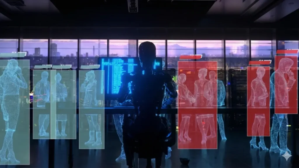
In the early stages of computer vision development, the focus was on images from cameras. It was believed that if the model learned to reliably recognize objects in 2D, this would be sufficient for most tasks. This approach worked for a long time in isolated scenarios: image classification, object search, simple detection. Problems began when systems started making decisions in real time and in real space.
For autonomous vehicles, a flat image proved to be fundamentally insufficient. A camera does not provide a direct answer to the question of the distance to an object. It does not indicate its actual size or the angle at which it is located relative to the trajectory of movement. Two objects may look almost identical in the frame, but be in completely different conditions in terms of safety.
Engineers quickly realized that without understanding the volume and orientation of objects, it is impossible to reliably solve the problems of tracking, trajectory prediction, and motion planning. A car driving ahead and a car crossing the road at an angle may occupy a similar area of the image, but require fundamentally different responses from the control system.
Cuboid annotation emerged as an attempt to bridge this gap between flat perception and three-dimensional reality. It allows an object to be recorded not only as a visual pattern, but as a physical entity in space. Cuboid specifies the minimum set of geometric information necessary for a machine to reason about a scene in terms of distances, directions, and dimensions.
It is important to understand that a cuboid is not an exact model of an object. It is a simplification, a compromise between the complexity of the real world and the limitations of sensors. It does not convey shape with high accuracy, does not take into account small details, and often ignores variations within a single class of objects. Nevertheless, it is this compromise that has proven to be practical and scalable for the autonomous driving industry.
The main thesis on which the further discussion is based is simple and at the same time inconvenient: it is not enough for autonomous vehicles to see a flat image. To operate safely in a complex and dynamic environment, the system must understand the volume and orientation of objects. Cuboid annotation has become the basic tool that allows us to move from image recognition to spatial perception of the scene.
The Anatomy of a Cuboid
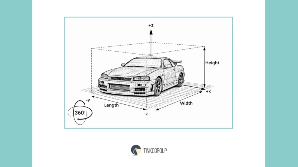
From a technical point of view, a cuboid looks extremely simple. It is described by a set of parameters that can be written down in a few lines: position, dimensions, orientation. It is this apparent simplicity that is often misleading. For engineers who are new to 3D annotation, a cuboid looks like a formal geometric construction. For those who have been working with autonomous systems for many years, it is one of the most sensitive elements of the entire perception chain.
Each cuboid parameter carries an assumption about how the object exists in space. An error in one value rarely remains local — it almost always spreads further, affecting tracking, motion prediction, and decision making.
Position: X, Y, Z Coordinates
The position of a cuboid is defined by coordinates in three-dimensional space. In most pipelines, these are the coordinates of the center of the object or a predefined reference point. Formally, these are just three numbers: X, Y, and Z. In practice, they represent a whole set of engineering solutions.
First, there is always the question of the coordinate system. Is the LiDAR coordinate system used, or the camera coordinate system, or the already merged space after sensor fusion? At this stage, the first inconsistencies between datasets begin to appear, especially if different teams or contractors are working under different agreements. Experienced engineers know that coordinate inconsistency is one of the most difficult sources of error to detect.
Second, the very idea of a “position point” is not as obvious as it seems. For symmetrical objects, the center works well. For elongated or asymmetrical objects, choosing the center can be a compromise. A car standing at an angle may have a geometric center at a point that does not correspond to its visual or dynamic “position” on the road.
In autonomous driving, the X, Y, and Z coordinates are used directly to calculate distances, approach speeds, and time to collision. Therefore, even small shifts in the cuboid position, especially at long distances, can lead to noticeable discrepancies in the system’s behavior.
Dimensions: Length, Width, Height
The dimensions of a cuboid — length, width, and height — describe the physical volume of an object. This is where the illusion of accuracy most often arises. The annotator thinks that if the box tightly covers the object, the task is solved. The engineer knows that the question is not how accurately the box is drawn, but how consistently these dimensions are interpreted by the model.
In real datasets, objects are rarely represented in their entirety. Part of an object may be hidden, cropped by the scene boundary, or simply absent from the point cloud due to the nature of LiDAR reflection. In such cases, cuboid dimensions inevitably become estimates. These estimates can be based on the object class, previous frames, or visual information from the camera.
Experienced teams try to develop strict rules: whether to use the “typical” size of the class or to try to restore the real volume based on partial data. But even the most detailed guidelines do not completely solve the problem. Different annotators interpret what a “tight box” means differently, especially in complex scenes.
Cuboid dimensions directly affect how the model perceives the space around an object. Overestimating dimensions leads to excessive safety zones, while underestimating them leads to risky decisions. This is why errors in the length or width of a car often manifest themselves not in detection metrics, but in the behavior of the system at the planning level.
Rotation: Yaw, Pitch, Roll
The orientation of a cuboid in space is the most complex and, at the same time, the most important parameter. It is defined by the yaw, pitch, and roll angles. In the context of autonomous driving, yaw — the angle of rotation of an object relative to the direction of movement — plays a key role.
Yaw determines which way the car is “looking,” whether it is moving along the trajectory or crossing it. Even a few degrees of yaw error can radically change the trajectory prediction, especially at high speeds. Engineers are well aware of cases where the model confidently detected an object but consistently misjudged its direction, making tracking unstable.
Pitch and roll often seem secondary, especially in urban scenarios. But in real-world conditions, they begin to play a role on uneven roads, descents, ascents, and in situations with non-standard objects. Ignoring these parameters can lead to the accumulation of errors that remain unnoticed for a long time.
The biggest problem with cuboid orientation is that it is rarely read directly from the data. Most often, it is an interpretation based on a combination of point cloud geometry and visual context. This is where the annotator’s experience and the clarity of the rules become critical.
Ultimately, cuboid anatomy is not just a list of parameters. It is a set of assumptions about how an object exists and behaves in a three-dimensional world. The more complex the scene, the more responsibility each of these parameters carries. And the longer an engineer works with autonomous systems, the less likely they are to perceive a cuboid as a “simple box.”
Cuboid vs. 3D Bounding Box (Clarifying Terminology)
In technical discussions, documentation, and even within engineering teams, the terms cuboid and 3D bounding box are used almost interchangeably. Formally, this is acceptable, and in most working scenarios, the difference between them is not significant. However, experience shows that confusion in terminology often reflects a deeper misunderstanding of what exactly the markup solves.
Historically, the term bounding box came from 2D computer vision, where it referred to the minimum rectangle encompassing an object in an image. When the industry began to transition to three-dimensional perception, this term was mechanically extended to the third dimension. This is how the 3D bounding box came about. The name stuck, even though it was no longer essentially a frame, but a three-dimensional geometric structure.
The word cuboid was more often used to emphasize the three-dimensional nature of this structure. It indicated that the object was described as a box with volume, rather than a projection onto a plane. Over time, the difference faded, and both terms came to mean the same thing — a parameterized three-dimensional box tied to an object in a scene. Let’s compare 2D vs 3D bounding box.
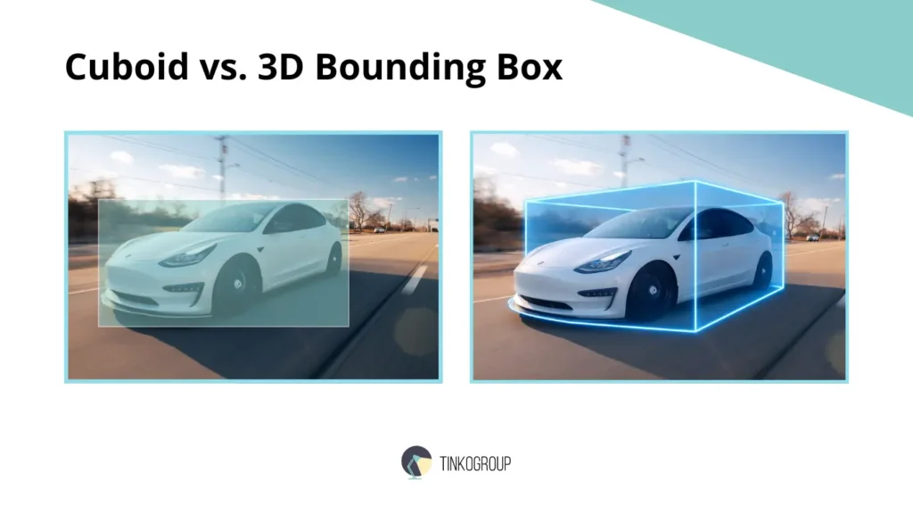
2D Bounding Box
A 2D bounding box is a flat rectangle defined by coordinates on an image. It answers a very limited set of questions: where the object is in the frame and what area of the image it occupies. In early computer vision systems, this was sufficient for classification and simple detection tasks.
However, a 2D bounding box does not contain any information about the depth, actual size, or orientation of the object. It does not allow you to distinguish between a close object and a distant one, does not give an understanding of its physical volume, and does not tell you how the object is oriented relative to the scene. That is why 2D markup quickly reached its limits when it came to systems that make decisions in real space.
These limitations were discussed in detail in earlier articles on 2D markup and its application in computer vision. In practice, engineers quickly come to the conclusion that a 2D bounding box is only suitable as an auxiliary tool or as part of a more complex pipeline.
3D Bounding Box / Cuboid
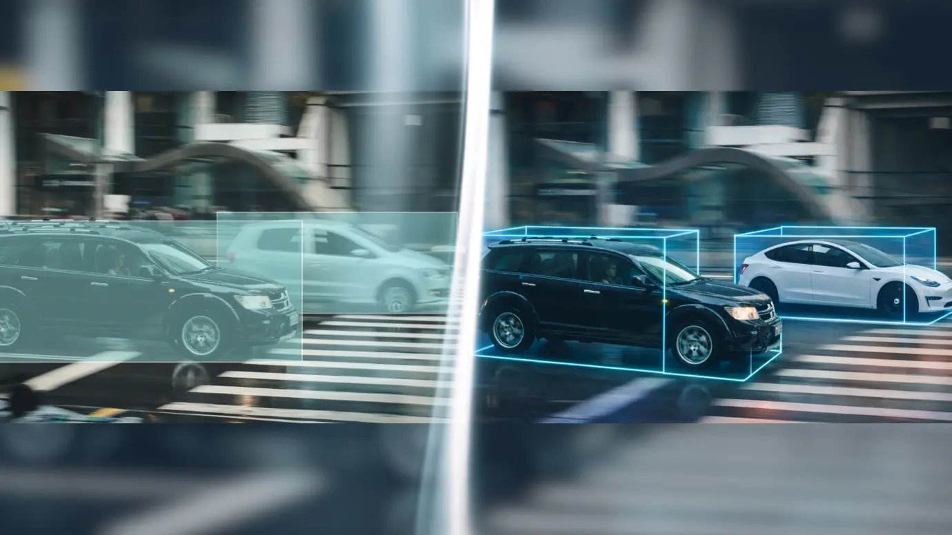
A 3D bounding box, or cuboid, is a three-dimensional box that describes an object in three-dimensional space. Unlike 2D annotation, it carries information not only about the position of the object in the frame, but also about its distance, size, and orientation.
It is important to understand that a cuboid does not seek to accurately replicate the shape of an object. Its task is to define the minimum geometric envelope sufficient for spatial reasoning. In this sense, a cuboid is a compromise between accuracy and computational practicality.
In autonomous driving engineering pipelines, a cuboid is used as a basic primitive. It forms the basis for algorithms for tracking, speed estimation, trajectory prediction, and decision making. This is why the terms 3D bounding box and cuboid are almost indistinguishable in real-world applications: both refer to the same tool that performs the same function.
Nevertheless, experienced engineers often intuitively use the word cuboid when they want to emphasize the physical nature of an object and its volume in space, and 3D bounding box when they talk about the formal data structure or annotation format. This difference is not fixed in standards, but it reflects the practical thinking of people who work with three-dimensional scenes on a daily basis.
Ultimately, debates about terminology are rarely productive. What matters more than the name of the markup is how consistently and meaningfully it is applied. Regardless of the name, the cuboid or 3D bounding box remains a key element in the transition from flat perception to understanding the three-dimensional world.
Input Data: Working with LiDAR and Point Clouds
Cuboid annotation is almost never based solely on camera images. Cameras provide visual context, but they do not provide reliable geometry. In autonomous driving systems, the main source of spatial information is the point cloud obtained from LiDAR sensors. It is on this data that most of the cuboid annotation is based.
Reliable Data Services Delivered By Experts
We help you scale faster by doing the data work right - the first time

Why Cuboids Are Drawn on Point Clouds and Not Just on Cameras
Engineers quickly realize that relying solely on images creates an illusion of accuracy. Despite its sparseness and noise, a point cloud provides something that a camera does not: direct distance measurement.
The main reasons for using point cloud data are:
- A point cloud directly reflects the three-dimensional structure of the scene.
- The distance to an object is measured rather than estimated based on indirect characteristics.
- The geometry of the scene remains stable when lighting changes.
- A cuboid can be tied to physical space rather than to an image projection.
For this reason, images are more often used as a supplementary source of information rather than as a basis for marking.
LiDAR Data and LiDAR annotation
LiDAR data is a set of points in three-dimensional space, each of which is the result of a laser pulse reflection. Unlike images, there are no continuous surfaces, contours, or object boundaries. There are only discrete reflections.
In the LiDAR annotation process, the annotator actually solves the reconstruction problem:
- determining which points belong to the same object;
- separating the object from the background and noise;
- mentally reconstructing the shape from incomplete data.
This process is rarely straightforward. Especially in complex scenes, the annotator has to rely not only on geometry, but also on experience:
- what cars usually look like at this distance;
- where reflections from the road or fences most often occur;
- which structures are typical sensor artifacts.
That is why the quality of LiDAR annotation depends heavily not only on the tools, but also on the training of the annotators.
Sensor Fusion: Camera + LiDAR
To compensate for the limitations of each individual sensor, most AV pipelines use sensor fusion. Cameras and LiDAR complement each other, creating a more stable representation of the scene.
The role of each source in the cuboid annotation process:
- the camera provides color, texture, and semantic cues;
- LiDAR provides accurate depth and spatial structure;
- combined data allows for more accurate determination of object boundaries and orientation.
In practice, sensor fusion is rarely perfectly synchronized. Small desynchronizations between sensors, differences in frame rates, and calibration errors inevitably affect the annotation. Experienced engineers know that an “ideal cuboid” drawn without taking these factors into account can be more harmful than one that is slightly inaccurate but consistent with real data.
The Annotation Workflow for Cuboids
Cuboid annotation is not a mechanical operation, but a process that requires experience, attention, and constant verification. On the surface, it may seem simple: take a point cloud annotation, draw a box around the object, assign an ID. In reality, each step has its own nuances, which engineers who have worked with perception data in autonomous driving know from experience.
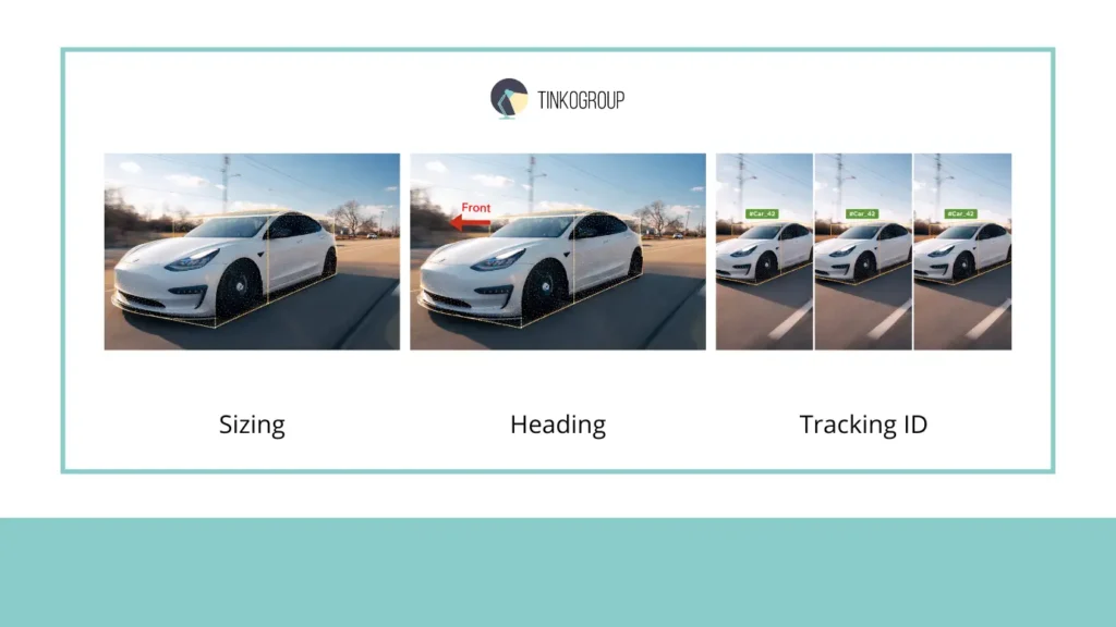
Sizing: “Tight” Box
The first rule of cuboid annotation is that the box must be “tight,” i.e., it must cover the object as tightly as possible. It would seem that what could be easier? In practice, this is far from the case. Point clouds are always sparse and noisy: distant objects are represented by a dozen scattered points, and some surfaces may not be captured by the sensor at all.
Engineers note that a tight box here is not absolute accuracy, but a compromise between:
- the maximum possible correspondence to the physical object;
- LiDAR and camera data limitations;
- the needs of downstream models (tracking, motion prediction).
If the box is too small, the model underestimates the object and may “miss” the danger. If it is too large, a false danger zone is created, which impairs the system’s performance. Real annotators learn to see this balance and do it consciously, not mechanically.
Heading: Front of the Object
The next critical element is cuboid orientation or heading. In particular, it is important to note where the “front” of the object is. This is especially critical for cars, motorcycles, and pedestrians moving in space.
Errors in determining the heading lead to serious consequences:
- tracking begins to jerk, especially when changing lanes;
- motion prediction becomes incorrect;
- the system may make the wrong decision about a safe distance.
Engineers know that the heading is sometimes difficult to determine even visually. Often, it is necessary to use:
- the context of the scene (which lane, direction of movement);
- previous tracking frames;
- the annotator’s experience and templates for certain classes of objects.
Thus, marking the front is not just an arrow on a box, but a strategic decision that affects the entire perception pipeline.
Tracking ID: Object Identity
The last key element of the workflow is assigning a Tracking ID. Cuboid must maintain the identity of an object as it moves through a sequence of frames. In practice, this is more difficult than it seems.
Problems arise when:
- occlusion occurs, when an object is temporarily hidden;
- objects intersect, when several cars are moving close together;
- LiDAR errors and ghost points occur, which can “split” an object into several cuboids.
Experienced annotators use various strategies:
- they preserve the ID even when visibility is temporarily lost;
- using time stamps and previous trajectories for verification;
- reconciling IDs between LiDAR and camera during sensor fusion.
Tracking ID is not just an identifier. It is the basis of tracking, and the stability of the perception model in a dynamic scene directly depends on its correctness.
Challenges in Cuboid Annotation
Cuboid annotation often seems simple from a formal point of view: there is an object, there is a box, there are parameters. In practice, however, it is one of the most difficult stages of data preparation for perception systems. Errors and compromises at this stage directly affect the behavior of an autonomous vehicle, and engineers know that even a small inaccuracy can result in unstable tracking or incorrect trajectory prediction. Below are the main challenges faced by annotators and engineers.
Sparse Data: Objects “on the Edge of Visibility”
Distant objects in a point cloud are often represented by only a few points. At first glance, this seems like a minor problem, but this is where most systematic errors originate.
Engineers note that sparse data leads to the following difficulties:
- it is impossible to unambiguously determine the boundaries of an object;
- orientation (yaw) is often guessed rather than measured;
- tight-box becomes more of a guess than an accurate annotation.
For example, a car at a distance of 50–70 meters in an urban scenario may be displayed as 10–15 points. The annotator must decide how to restore the full volume based on the object class, experience, and previous tracking frames. This process requires not formal rules, but a practical understanding of how objects look in LiDAR.
Experienced teams always double-check: if the tight box on a distant object seems “too confident,” it is almost always a reason to review the annotation. Such errors can cause false alarms or, conversely, missed hazards.
Occlusion & Truncation: Objects Partially Hidden by the Scene
Occlusion and truncation occur when objects are partially hidden behind other objects, walls, or other vehicles. This is a particularly painful issue for cuboid annotation.
The main challenges:
- How do you determine the full volume of an object if only part of it is visible?
- Should you extrapolate the missing part based on class averages?
- How do you avoid systematic biases in downstream models?
Experienced engineers note that occlusion is not just a visual flaw. It directly affects tracking. The model may “catch up” with the object based on assumptions rather than actual data, leading to track jitter, speed errors, and trajectory prediction errors.
In real projects, the solution is usually a compromise: annotators mark the visible part, create a rule for restoring hidden geometry, and check the impact on simulations. No formal instructions give perfect results — only experience allows you to minimize errors.
Ghost Points: Noise Masquerading as Objects
Ghost points are reflections from glass, road signs, metal surfaces, or even rain. They create “ghost points” that can be mistaken for real objects.
The main problem is that ghost points rarely look like random noise. They:
- have a density similar to that of an object;
- can move in sync with vehicles;
- appear consistently in several consecutive frames.
For an inexperienced annotator, this is a source of constant confusion. Experienced engineers know that incorrectly marked ghost points lead to “phantom” objects in the model, which create false alarms or block decision-making on the road.
In industrial practice, ghost points require careful verification and cross-checking of data with the camera and previous tracking frames. Even modern sensor fusion tools do not always help 100%, so human experience is indispensable here.
When Problems Overlap
The most difficult scenes are not individual challenges, but combinations: sparse data + occlusion + ghost points. In such conditions, the cuboid ceases to be just a box and becomes an engineering interpretation of space.
Annotators and engineers are forced to balance between:
- maximum accuracy;
- acceptable model confidence level;
- safety and reliability of the perception pipeline.
Experience shows that it is in these borderline cases that the quality of the entire system is determined. An error on the visible part of an object or incorrect cuboid orientation on a distant object can lead to unpredictable AV behavior.
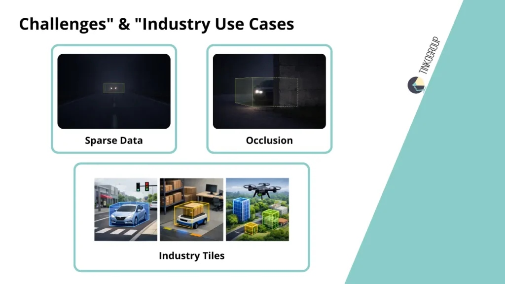
Industry Use Cases
Cuboid annotation does not exist in a vacuum. Its value only becomes apparent when data enters real systems that must make decisions in a dynamic environment. Engineers working with perception in autonomous driving, robotics, and drones know that every error in annotation quickly manifests itself in practice. Below are the main areas of application for cuboid, with real engineering nuances.
Autonomous Driving
In autonomous driving, cuboid annotation is the basis for all spatial reasoning by the machine. A correctly marked cuboid allows you to evaluate:
- the position of the vehicle on the road;
- its orientation relative to the trajectory of movement;
- potential intersections of trajectories with other objects.
The use of autonomous driving data with cuboid annotation allows models to accurately calculate the distance to objects and predict their movement. In practice, this is critical for preventing collisions.
Engineers note that even a small error in the size or heading cuboid of a car traveling at 50–70 km/h can cause the model to incorrectly predict the trajectory, creating false alarms or missing potential hazards. Therefore, all cuboids undergo rigorous quality control, and complex scenes with occlusion and sparse data are tested particularly thoroughly.
Cuboid annotation here is not just a visual marker, but a risk minimization tool. It allows the system to understand the three-dimensional position of objects and make decisions as if the machine could “see” the world in three dimensions.
Robotics
In robotics, especially in the field of indoor navigation, cuboid annotation is used to enable robots to move safely in confined spaces. For example, a robot vacuum cleaner or service robot in an office must navigate around furniture, doorways, and people.
Cuboid allows objects to be described not as “points” on a map, but as three-dimensional obstacles that cannot be crossed. Engineers note that marking accuracy is no less important for robots than it is for cars: a cuboid that is too small leads to collisions, while one that is too large leads to overly conservative trajectories, where the robot begins to avoid even free space.
In addition, indoor scenes often contain small objects, transparent surfaces, and complex furniture configurations, which makes the annotation task particularly difficult. Here, the annotator’s experience and understanding of robot behavior play a key role.
Drones
In the drone industry, cuboid annotation is used for aerial 3d bounding box object detection. Drones must detect buildings, trees, people, and vehicles from the air, which imposes its own limitations:
- objects may be visible from different angles;
- sensor fusion with a camera and LiDAR is often the only way to obtain accurate geometry;
- drone movements add additional complexity to maintaining Tracking ID for moving cuboids.
Engineers working with drones know that errors in cuboid annotation lead to false positives or missed objects, especially at high flight speeds. Correct annotation allows models to estimate the size and orientation of objects in three-dimensional space and make safe decisions about flight paths.
Conclusion
Cuboid annotation has long established itself as the gold standard for perception models. It allows autonomous driving systems, robotics, and unmanned drones to see not just objects in an image, but their actual volume, position, and orientation in space.
Engineers with many years of experience note that it is cuboid annotation that provides the minimum necessary geometric basis for all downstream processes:
- object tracking;
- trajectory prediction;
- distance and traffic safety assessment;
- route and maneuver planning.
Without high-quality cuboid annotations, the perception system begins to rely on guesswork. Errors at the annotation stage manifest themselves in the behavior of the model, sometimes in extremely unexpected ways: incorrect orientation, underestimation of dimensions, or omission of objects at long distances can lead to unpredictable consequences in the real world.
At the same time, cuboid annotation is not magic. It requires the experience of annotators, competent use of sensor fusion, and careful work with LiDAR and point cloud data. It is a compromise between physical reality and sensor limitations, but it is this compromise that allows the creation of reliable perception models that can be implemented in real systems.
For engineers, teams, and companies that want to improve the accuracy and reliability of their perception models, cuboid annotation is a basic tool without which the further development of autonomous systems is simply impossible.
If you want to take your perception projects to the next level, learn more about professional cuboid annotation services, and get support from experienced specialists, we recommend visiting the Tinkogroup annotation services. Here you will find everything you need for high-quality and safe implementation of 3D annotations in your systems.
Cuboid annotation is not just a markup. It is the foundation on which the future of autonomous perception and safe solutions in the real world is built.
What is the difference between a 3D Bounding Box and a Cuboid?
In most technical contexts, these terms are used interchangeably to describe a three-dimensional box with length, width, height, and orientation. However, “3D Bounding Box” often refers to the formal data structure in a dataset, while “Cuboid” is used to emphasize the physical volume and spatial orientation of an object in a 3D scene.
Why is LiDAR preferred over 2D cameras for cuboid annotation?
While cameras provide rich visual context like color and texture, they do not provide direct distance measurements or accurate 3D geometry. LiDAR sensors generate point clouds that allow for precise measurement of an object’s distance, actual physical size, and orientation, which are critical for safe autonomous navigation.
How do occlusion and sparse data affect cuboid annotation quality?
Occlusion occurs when an object is partially hidden, forcing annotators to estimate its full volume based on experience or previous frames. Sparse data occurs at long distances where LiDAR points are few; in these cases, maintaining a “tight” box and correct heading becomes a complex engineering interpretation rather than simple marking, directly impacting the safety of trajectory prediction.